在线时间972 小时
UID1694538
注册时间2018-5-21
NXP金币2185
TA的每日心情 | 奋斗
6 小时前 |
|---|
签到天数: 2001 天 [LV.Master]伴坛终老
金牌会员
 
- 积分
- 11921
- 最后登录
- 2024-4-25
|
本帖最后由 yinwuqing 于 2019-3-31 18:07 编辑
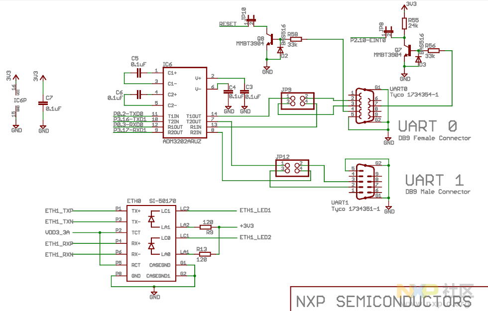
根据官方给出的原理图,结合板子实物,我们知道LPC1768是提供两串口,UART0是母头型插口,而UART1与两个CAN总线的接口一样,是公头型的。此次实验用到是UART0打印调试信息,为此特意从网上买了个USB转9针串口的数据线。如下图所示:

然后将JP9的插针用跳线帽连接好,接下来在KEIL中搭建好软件平台开发包,首先新建工程选择LPC1768的芯片型号,然后勾选微控制器软件接口标准库如下下图所示:

编写串口实现函数,并在“RTE_Device.h”头文件中将UART0使能设置打开,将字符输入到LCD显示屏上并经UART0打印输出到串口调试助手上。部分代码如下:
- #include "LPC17xx.h" /* LPC17xx Definitions */
- #include "GPIO_LPC17xx.h"
- #include "PIN_LPC17xx.h"
- #include "UART_LPC17xx.h"
- #include <string.h>
- #include <stdio.h>
- /*---------------------------------------------------------------------------*
- * Constants & Macros:
- *---------------------------------------------------------------------------*/
- #define INSTR_CLEAR 0x01 // 1.53 ms
- #define INSTR_RETURN_HOME(settings) 0x02 // 1.53 ms
- #define INSTR_ENTRY_MODE(settings) (0x06|(settings)) // 39 uS
- #define IENTRY_INCREMENT (1<<1)
- #define IENTRY_DECREMENT (0<<1)
- #define IENTRY_SHIFT_ON (1<<0)
- #define IENTRY_SHIFT_OFF (0<<0)
- #define INSTR_DISPLAY(settings) (0x08|(settings)) // 39 uS
- #define IDISPLAY_ON (1<<2)
- #define IDISPLAY_OFF (0<<2)
- #define IDISPLAY_CURSOR_ON (1<<1)
- #define IDISPLAY_CURSOR_OFF (0<<1)
- #define IDISPLAY_BLINK_ON (1<<0)
- #define IDISPLAY_BLINK_OFF (0<<0)
- #define INSTR_SHIFT(settings) (0x10|(settings)) // 39 uS
- #define ISHIFT_SCREEN (1<<3)
- #define ISHIFT_CURSOR (0<<3)
- #define ISHIFT_RIGHT (1<<2)
- #define ISHIFT_LEFT (0<<2)
- #define INSTR_FUNC(settings) (0x20|(settings)) // 39 uS
- #define IFUNC_8BIT (1<<4)
- #define IFUNC_4BIT (0<<4)
- #define IFUNC_TWO_LINE (1<<3)
- #define IFUNC_ONE_LINE (0<<3)
- #define IFUNC_DISPLAY_ON (1<<2)
- #define IFUNC_DISPLAY_OFF (0<<2)
- #define INSTR_SET_CGRAM_ADDR(x) (0x40|((x)&0x3F)) // 39 uS
- #define INSTR_SET_DDRAM_ADDR(x) (0x80|((x)&0x7F)) // 39 uS
- #define LUMEX_SO2004DSR_NUM_COLUMNS 20
- #define LUMEX_SO2004DSR_NUM_ROWS 4
- #define LED_PORT 0
- #define LED_PIN 7
- uint32_t LEDOn, LEDOff;
- uint32_t uTimeCnt=0;
- extern ARM_DRIVER_USART Driver_USART0;
- static void USART0_Callback(uint32_t event);
- static uint8_t rxBuffer[8] = {0};
- static uint8_t txBuffer[1024] = {0};
- struct LPC_PORT
- {
- uint32_t uPort;
- uint32_t uPin;
- };
- struct LPC_PORT LCD_Pin[11] =
- {
- {2,0},
- {2,1},
- {2,2},
- {2,3},
- {2,4},
- {2,5},
- {2,6},
- {2,7}, //data
- {2,8}, //rs
- {0,22}, //rw
- {2,10}, //enable
- };
- int32_t Delayms(uint32_t ms)
- {
- int n,m=100000;
- for(n=0;n<ms;n++)
- {
- while(m)
- {
- m--;
- }
- }
- return 0;
- }
- /*----------------------------------------------------------------------------
- SysTick IRQ Handler
- *----------------------------------------------------------------------------*/
- void SysTick_Handler (void)
- {
- static uint32_t ticks;
- switch(ticks++)
- {
- case 0: LEDOn = 1; break;
- case 5: LEDOff = 1; break;
- case 9: ticks = 0; break;
- default:
- if (ticks > 10)
- {
- ticks = 0;
- }
- }
- }
- int32_t LED_Initialize(void)
- {
- /* Enable GPIO clock */
- GPIO_PortClock (1);
- /* Configure pins: Output Mode with Pull-down resistors */
- PIN_Configure (LED_PORT, LED_PIN, PIN_FUNC_0, PIN_PINMODE_PULLDOWN, PIN_PINMODE_NORMAL);
- GPIO_SetDir (LED_PORT, LED_PIN, GPIO_DIR_OUTPUT);
- GPIO_PinWrite (LED_PORT, LED_PIN, 0);
- return 0;
- }
- /*----------------------------------------------------------------------------
- Main function
- *----------------------------------------------------------------------------*/
- int main (void)
- {
- SystemCoreClockUpdate(); /* Update system core clock */
- SysTick_Config(SystemCoreClock/10); /* Generate interrupt each 10 ms */
- LED_Initialize(); /* LED Initialization */
- LCD_Init();
- LCD_WR_Str("Welcome to NXP Community!");
- Driver_USART0.Initialize(USART0_Callback);
- Driver_USART0.PowerControl(ARM_POWER_FULL);
- Driver_USART0.Control(ARM_USART_MODE_ASYNCHRONOUS |
- ARM_USART_DATA_BITS_8 |
- ARM_USART_PARITY_NONE |
- ARM_USART_STOP_BITS_1 |
- ARM_USART_FLOW_CONTROL_NONE, 115200);
- Driver_USART0.Control(ARM_USART_CONTROL_TX,1);
- Driver_USART0.Control(ARM_USART_CONTROL_RX,1);
- Driver_USART0.Receive(rxBuffer,sizeof(rxBuffer));
- while (1)
- {
- if(LEDOn)
- {
- LEDOn = 0;
- GPIO_PinWrite(LED_PORT, LED_PIN, 1); /* Turn specified LED on */
- Driver_USART0.Send("Welcome to NXP Community!",25);
- }
- if (LEDOff)
- {
- LEDOff = 0;
- GPIO_PinWrite(LED_PORT, LED_PIN, 0); /* Turn specified LED off */
- }
- }
- }
- static void USART0_Callback(uint32_t event)
- {
- if(event & ARM_USART_EVENT_RECEIVE_COMPLETE)
- {
- Driver_USART0.Control(ARM_USART_ABORT_RECEIVE, 1);
- uint32_t length = Driver_USART0.GetRxCount();
- memcpy(txBuffer, rxBuffer, length);
-
- Driver_USART0.Send(txBuffer, length);
- Driver_USART0.Receive(rxBuffer, sizeof(rxBuffer));
- }
- }
|
|
 /4
/4 