本帖最后由 rongxiangjun 于 2021-3-4 16:07 编辑
LPC55xx的ADC是一种全新的IP,它支持单端模拟信号采样,差分模拟信号采样,采样频率可以达到1MSPS。它支持软件触发和硬件触发,如外部GPIO 端口0 和端口1的引脚都可以触发ADC, 换句话说可以用外部信号触发ADC。 CTimer及SCT模块都可以产生触发信号触发ADC采样, 用这种方法可以保证ADC的等间隔采样。
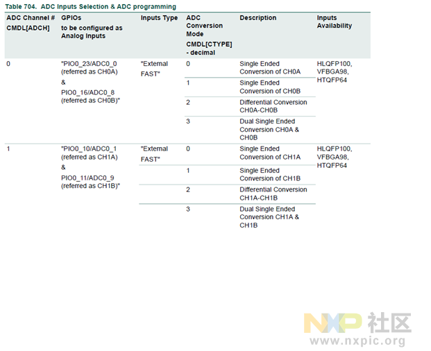
这是ADC的模拟信号的引脚定义:

ADC触发信号:
在SDK example中,我们有ADC采样的例子, 但这个例子是每次采样只能采样一个通道, 基于该例子做了功能扩展,扩展后单次软件触发可以采样多个模拟通道。 就硬件而言,每一个ADC触发源对应一个ADCTrigger Control Register, 总共有16 ADC Trigger ControlRegisters TCTRL[0:15]。 但是LPC55S69总共有13个硬件触发源,所以剩余的3个ADC TriggerControl Registers TCTRL[13:15]只可以用作软件触发。
就每一个Trigger Control Register 都绑定一个ADC command buffer register, 且只能绑定一个 ADCcommand buffer register。 对于LPC55xx,总共有15个ADC command buffer registers: CMDH[1:15]/CMDL[1:15],其中CMDH[x]/CMDL[x]是一组,两个总共有64位。每一组ADC command buffer register定义了要采样的模拟通道,模拟通道的特性(单端,差分),分辨率,采样时间,采样的平均数,以及要链接的下一个ADC command buffer register。每一个ADC commandbuffer register只能定义了一个模拟通道,如果单次触发要采样多个通道,就要使用ADCcommand buffer register的链接功能,将多个ADC command bufferregister链接起来。
如下图所示,CMDH[1:15]的第24到27是Next Command Select, 用这几位就可以实现级联。
这是一个列子,用户想用软件触发,采样3个通道:CH0A(ADC0_0), CH2A(ADC0_2), CH3A(ADC0_3).
lpadc_config_t mLpadcConfigStruct;
ADCPinAssignment();
/* Set clock source for ADC0 */
CLOCK_SetClkDiv(kCLOCK_DivAdcAsyncClk, 16U, true);
CLOCK_AttachClk(kMAIN_CLK_to_ADC_CLK);
/* Disable LDOGPADC power down */
POWER_DisablePD(kPDRUNCFG_PD_LDOGPADC);
LPADC_GetDefaultConfig(&mLpadcConfigStruct);
mLpadcConfigStruct.enableAnalogPreliminary = true;
#if defined(DEMO_LPADC_VREF_SOURCE)
mLpadcConfigStruct.referenceVoltageSource = DEMO_LPADC_VREF_SOURCE;
#endif /* DEMO_LPADC_VREF_SOURCE */
#ifdefined(FSL_FEATURE_LPADC_HAS_CTRL_CAL_AVGS) &&FSL_FEATURE_LPADC_HAS_CTRL_CAL_AVGS
mLpadcConfigStruct.conversionAverageMode = kLPADC_ConversionAverage128;
#endif /*FSL_FEATURE_LPADC_HAS_CTRL_CAL_AVGS */
mLpadcConfigStruct.FIFO0Watermark=2;
LPADC_Init(DEMO_LPADC_BASE, &mLpadcConfigStruct);
SDK为Trigger ControlRegister定义如下的结构:
typedef struct
{
uint32_t targetCommandId; /*!< Select the command from commandbuffer to execute upon detect of the associated
triggerevent. */
uint32_t delayPower; /*!< Select the trigger delay duration to wait at thestart of servicing a trigger event.
When thisfield is clear, then no delay is incurred. When this field is set to a non-zero
value, theduration for the delay is 2^delayPower ADCK cycles. The available value range
is 4-bit. */
uint32_t priority; /*!< Sets the priority of the associatedtrigger source. If two or more triggers have the same
priority levelsetting, the lower order trigger event has the higher priority. The lower
value for thisfield is for the higher priority, the available value range is 1-bit. */
#if(defined(FSL_FEATURE_LPADC_FIFO_COUNT) && (FSL_FEATURE_LPADC_FIFO_COUNT== 2))
uint8_t channelAFIFOSelect; /* SAR Result Destination For Channel A. */
uint8_t channelBFIFOSelect; /* SAR Result Destination For Channel B. */
#endif /* FSL_FEATURE_LPADC_FIFO_COUNT */
bool enableHardwareTrigger; /*!< Enable hardware trigger source toinitiate conversion on the rising edge of the
inputtrigger source or not. THe software trigger is always available. */
} lpadc_conv_trigger_config_t;
用户可以声明一个以此结构的变量,然后初始化此变量,且用下列代码初始化相应的TriggerControl Register。
lpadc_conv_trigger_config_t mLpadcTriggerConfigStruct;
/*Set trigger configuration. */
LPADC_GetDefaultConvTriggerConfig(&mLpadcTriggerConfigStruct);
mLpadcTriggerConfigStruct.targetCommandId = DEMO_LPADC_USER_CMDID1; /* CMD15 is executed. */
mLpadcTriggerConfigStruct.enableHardwareTrigger = false;
LPADC_SetConvTriggerConfig(DEMO_LPADC_BASE,0U, &mLpadcTriggerConfigStruct);/* Configuratethe trigger0. */
在以上的代码中, 初始化了ADC Trigger Control Registers0寄存器
下面的代码就是介绍基于SDK的函数,如何使用Command buffer的链接功能。首先定义一个结构和基于此结构的3个变量。
typedef struct
{
#ifdefined(FSL_FEATURE_LPADC_HAS_CMDL_CSCALE) &&FSL_FEATURE_LPADC_HAS_CMDL_CSCALE
lpadc_sample_scale_mode_tsampleScaleMode; /*!<Sample scale mode. */
#endif /*FSL_FEATURE_LPADC_HAS_CMDL_CSCALE */
lpadc_sample_channel_mode_t sampleChannelMode; /*!< Channel samplemode. */
uint32_t channelNumber; /*!< Channel number, select the channelor channel pair. */
uint32_t chainedNextCommandNumber; /*!< Selects the next command to beexecuted after this command completes.
1-15 is available, 0 is to terminatethe chain after this command. */
bool enableAutoChannelIncrement; /*!< Loopwith increment: when disabled, the "loopCount" field selects thenumber
oftimes the selected channel is converted consecutively; when enabled, the
"loopCount" field defines how many consecutive channels areconverted as part
of the commandexecution. */
uint32_t loopCount; /*!< Selects how many times this commandexecutes before finish and transition to the next
command or Idlestate. Command executes LOOP+1 times. 0-15 is available. */
lpadc_hardware_average_mode_t hardwareAverageMode; /*!< Hardware average selection. */
lpadc_sample_time_mode_t sampleTimeMode; /*!< Sample time selection. */
lpadc_hardware_compare_mode_t hardwareCompareMode; /*!< Hardware compare selection. */
uint32_t hardwareCompareValueHigh; /*!< Compare Value High. The availablevalue range is in 16-bit. */
uint32_t hardwareCompareValueLow; /*!<Compare Value Low. The available value range is in 16-bit. */
#if defined(FSL_FEATURE_LPADC_HAS_CMDL_MODE)&& FSL_FEATURE_LPADC_HAS_CMDL_MODE
lpadc_conversion_resolution_mode_t conversionResolutionMode; /*!< Conversion resolution mode. */
#endif /* FSL_FEATURE_LPADC_HAS_CMDL_MODE*/
#ifdefined(FSL_FEATURE_LPADC_HAS_CMDH_WAIT_TRIG) &&FSL_FEATURE_LPADC_HAS_CMDH_WAIT_TRIG
bool enableWaitTrigger; /*!< Wait for trigger assertion before execution: whendisabled, this command will be
automatically executed; whenenabled, the active trigger must be asserted again before
executing thiscommand. */
#endif /* FSL_FEATURE_LPADC_HAS_CMDH_WAIT_TRIG */
} lpadc_conv_command_config_t;
lpadc_conv_command_config_tmLpadcCommandConfigStruct0,mLpadcCommandConfigStruct1,mLpadcCommandConfigStruct2;
LPADC_GetDefaultConvCommandConfig(&mLpadcCommandConfigStruct0);
mLpadcCommandConfigStruct0.channelNumber = DEMO_LPADC_USER_CHANNEL; //adc channel0
mLpadcCommandConfigStruct0.chainedNextCommandNumber=DEMO_LPADC_USER_CMDID2;
LPADC_SetConvCommandConfig(DEMO_LPADC_BASE, DEMO_LPADC_USER_CMDID1,&mLpadcCommandConfigStruct0);
///////////////Rong addedanother adc channel
LPADC_GetDefaultConvCommandConfig(&mLpadcCommandConfigStruct1);
mLpadcCommandConfigStruct1.channelNumber = DEMO_LPADC_USER_CHANNEL+1; //DEMO_LPADC_USER_CHANNEL+1=1, adc channel1
mLpadcCommandConfigStruct1.chainedNextCommandNumber=DEMO_LPADC_USER_CMDID3;
LPADC_SetConvCommandConfig(DEMO_LPADC_BASE,DEMO_LPADC_USER_CMDID2, &mLpadcCommandConfigStruct1);
LPADC_GetDefaultConvCommandConfig(&mLpadcCommandConfigStruct2);
mLpadcCommandConfigStruct2.channelNumber = DEMO_LPADC_USER_CHANNEL+2; //DEMO_LPADC_USER_CHANNEL+1=1, adc channel1
mLpadcCommandConfigStruct2.chainedNextCommandNumber=0;
LPADC_SetConvCommandConfig(DEMO_LPADC_BASE,DEMO_LPADC_USER_CMDID3, &mLpadcCommandConfigStruct2);
注意最后一个Command Buffer的链接 Command Buffer必须手机0, 0被认为是一个无效的Command Buffer.
mLpadcCommandConfigStruct2.chainedNextCommandNumber=0;
LPADC_DoSoftwareTrigger(DEMO_LPADC_BASE, 1U); /* 1U is trigger0 mask.*/
在初始化的代码中使用了ADC Trigger Control Registers0 寄存器,故用以上代码触发 ADC Trigger Control Registers0 寄存器来启动ADC转换。
void DEMO_LPADC_IRQ_HANDLER_FUNC(void)
{
static uint32_t index=0;
g_LpadcInterruptCounter++;
{
g_LpadcConversionCompletedFlag = true;
LPADC_GetConvResult(DEMO_LPADC_BASE,&g_LpadcResultConfigStruct, 0U);
resultArray[index][0]=g_LpadcResultConfigStruct;
LPADC_GetConvResult(DEMO_LPADC_BASE,&g_LpadcResultConfigStruct, 0U);
resultArray[index][1]=g_LpadcResultConfigStruct;
LPADC_GetConvResult(DEMO_LPADC_BASE,&g_LpadcResultConfigStruct, 0U);
resultArray[index][2]=g_LpadcResultConfigStruct;
index++;
if(index>=NUMBEROFSAMPLE)
{
__asm("nop"); //set breakpoint here
index=0;
}
}
|  /3
/3 